Ensign Cockpit Floor Project
The Problem
Over the past several years, it was becoming more and more evident that the cross braces (stringers) under the cockpit teak floor were becoming soft. Since my Ensign #557 was built forty years ago, this is not entirely unexpected. It was particularly noticeable where the bilge hatch assemblies were seated, and in a few locations where the screw fasteners into the stringers were separating. While I did not feel the floor was in danger of collapse, I did feel it was time to end my procrastination and correct the condition by replacing the cross braces. Besides, everyone needs a project to keep them occupied over the winter when they're not sailing.
The Game Plan
Even though the cross braces needed replacement, the teak floor itself was still in excellent condition in spite of 40 years of benign neglect. So the project objective was to replace the old stringers, and refasten the existing teak floor to the new replacement stringers. I did not want to completely disassemble the floor unit because I was concerned that this would add to the complexity of the project. Besides, I was concerned that I would never be able to put it all back together. So another project objective was to maintain the floor unit integrity during the stringer replacement process. This would be accomplished by removing the floor and stringers from the boat as a unit, replacing the stringers on a one-by-one basis, and reinstalling the refurbished floor back into the Ensign as a unit. My backup plan, in case of project disaster, was to simply order a replacement floor unit from Zeke Durica at Ensign Spars.
Floor Removal
Fleet member Duane Nealon had recently refurbished his Ensign #841 over the past year, and his experience was that the floor unit was not fastened to the hull and just lifted out. Based on that in-depth research, I was ready to charge ahead. The first step was to remove the seats and the shelf under the combing. This is a straight forward screw removal process which I had done a few years earlier in stripping and varnishing the seats over the winter. With the seats removed, the floor unit was fully exposed and ready for removal. I gave a few tugs at the rear of the assembly near the rudder post but not much was happening so I recruited an extra pair of hands. (Ironically, the extra hands belonged to Duane Nealon of the "not fastened to the hull" research.) With our combined efforts, the floor unit lifted quite easily, and with a few more twists and tugs, it was free of the hull and ready to be removed over the side. Examination of the unit showed it had indeed been secured to the hull by fiberglass cloth over the ends of the cross braces prior to the installation of the teak. These ends were so soft they had quickly crumbled. In addition, there were four long screws in the forwardmost cross brace which had been inserted from inside the cabin through the marine ply cross member under the doors. These screws were simply pulled through the ply by our twist and tug efforts. An examination of the unit cross braces showed that the replacement project was probably a bit overdue, although the forward stringer was in very good condition, and might not require replacement at this time.
Fig. 1 - Fiberglass caps inside hull which secured orignal cross braces.
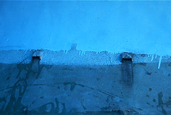
Fig. 2 - Screws inserted from inside cabin to secure forward cross brace.
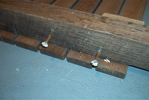
Fig. 3 - Poor condition of bilge access cross brace.
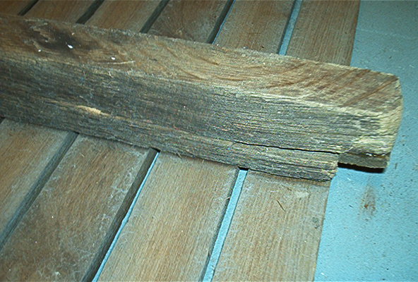
Fig. 4 - Cross brace more than ready for replacement.

Plug Removal
Removing the teak from the cross braces would require access to the screw heads which meant that the first step in the process was the removal of the wooden plugs which covered the screws. I chose to use a ¼ inch wood chisel to remove much of the material of the 3/8 inch plugs. I then used a variety of hand tools including a pick and pen knife to clear out the rest of the plug hole. A shop vac was used to remove the remaining debris.
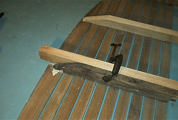
Screw Removal
Screw removal proved to be a major problem. The screws readily pulled free from the soft cross braces. However, they were firmly frozen to the teak. I used a small Dremel tool to clean the slot heads of the screws in their holes. Use of a conventional screw driver was futile, so I obtained an old fashioned brace and bit to get additional torque and downward pressure. Working on my targeted first cross brace, I was about fifty per cent successful in getting the screws to turn. I then turned the floor unit over so that the cross braces were now exposed. I easily pried the targeted cross brace from the unit which in turn left the screw ends exposed. A spacer was placed under the unit near the vicinity of the cross brace, and the screws which had turned were easily tapped out of their holes with a hammer. I attempted to turn the remaining screws with a vise grip, but the exposed ends just twisted off. I then used a punch and hammer, and a little more force, to drive these remaining screws out of their holes. This dual approach to screw removal ultimately was successful.
The New Cross Braces
My new cross braces were cut from white oak stock. My original plan was to custom cut and install the new stringers one by one as I removed each old stringer. After removing my targeted first stringer, and using it as a template for custom cutting the new stringer, I felt it would be more efficient to custom cut the other stringers at the same time. This was easily done by using the old stringers as a template while still installed. This also gave me the opportunity to test the fit and alignment of the new stringers in the hull of the boat prior to assembly. I checked the level of each stringer and also checked the alignment fore and aft along a pre-marked centerline. I was now ready to move ahead with the assembly process with some confidence that the final unit fit into the boat should not require major trim adjustment.
Fig. 5 - Old cross brace and its replacement.
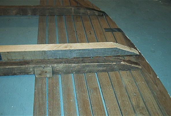
Fig. 6 - New cross brace in place.
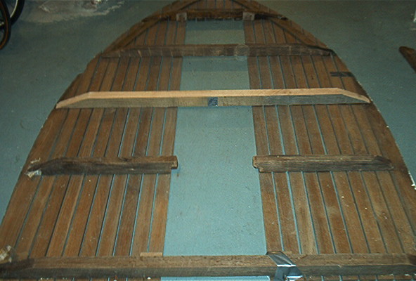
Fig. 7 - Old cross brace as a template for its replacement.
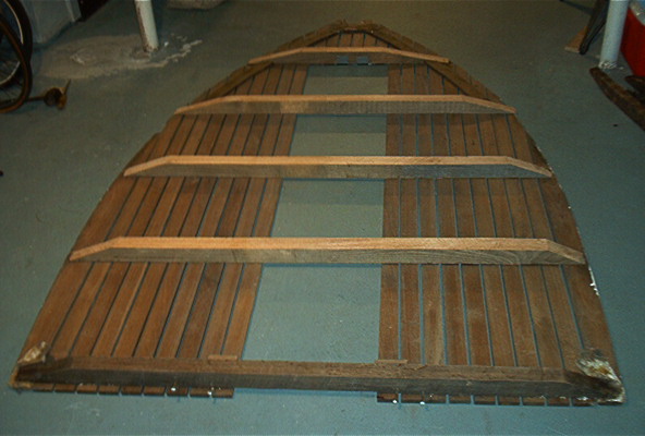
Cross Brace Installation
The installation of the new stringers was very straight forward as the new screws were inserted into the existing holes in the teak flooring. I used the pre-marked center line to assist in positioning the new stringers and also checked the alignment of the existing bilge access hatch assemblies to make sure they seated properly. I decided to keep the existing number one stringer in place since it was structurally sound, and I was concerned that any removal attempt would result in significant teak damage. I also decided not to cut out the center portion of stringer number two as I do not store anything in the bilge. If bilge access should become a problem in the future, I could always cut it, notch it, and reinstall the support braces. This approach also meant that the forward bilge hatch would require some modification as the center hatch brace would now interfere with the new full length stringer. I removed the brace with a wood chisel so as not to disturb the screws and plugs on the upper side. I then removed the exposed screw ends with a hack saw and recessed the ends with a Dremel tool. A new brace was added on either side of the new stringer from the underside to give the hatch added stability. I also removed a useless in-the-floor compass which was located between the two bilge hatches. This required the installation of new teak pieces which were supplied by Ensign Spars.
Fig. 8 - Replacement cross braces in place.
Finishing Up
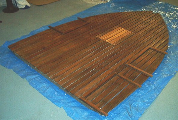
I obtained teak bungs (plugs) from Jamestown Distributors, used epoxy to set them in the recessed screw holes, and just hand sanded them flush. I had used a power pressure washer on the floor unit before removal which was quite successful in cleaning the teak. Since the teak was now clean for the first time in 40 years, I applied Teak Oil to the floor unit in anticipation of extending the teak life another 40 years.
Nothing left to do now except wait for Spring, and the installation of the floor unit back into the boat.
Fig. 9 - Finished project ready for installation.
Contact us if you'd like to learn more about Ensign sailing.