Ensign Mast Step Replacement
One of the few Achilles' Heels of the Ensign is the potential failure of the mast step. In my Ensign articles archives I have a 1976 article on the problem and repair, so it is not a new problem.
The common warning signs of an approaching problem are a need to take up a few more turns on the shroud turnbuckles and a collection of water around the mast step plate when the cuddy floor gets wet. I did not sense a turnbuckle take-up situation on my Ensign, but I did notice that water around the plate seemed to indicate that the plate was indented into the cuddy floor. Using the screwdriver handle test method, I got a nice sharp-sounding response when I tapped the floor up to the mast step area. A picture I was able to take when I did my cockpit floor project seemed to confirm that the floor was solid up to the first cross brace.
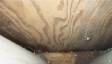
Figure 1. Photograph taken from underneath the cockpit sole looking forward. The first (aft) floor brace can be seen.
Around and ahead of the mast I got a dull thud. Also, forward of the mast, the cuddy floor was spongy. Thus I had the makings of a great over-the winter project. I concluded that the biggest challenge of the project would be to return the mast step and cuddy floor to their original positions. Thus a considerable portion of my project time (probably too much) was spent in measuring and leveling.
My Ensign is stored on a metal cradle with adjustable poppets so my first task was to make sure the boat was level. I used a conveniently long level at various spots on the boat until I was satisfied that it was as good as it would get. As a final confirmation step I dropped a plumb line from the forward center of the partner opening to the center of mast step plate. This would also be my gauge for the installation of the plate on the new floor when the projected was completed. When I removed the mast step plate, I also constructed a fixed gauge by inserting a length of wood through the partner opening to the cuddy floor and screwing on a cross piece above the opening. This would give me an indication of where the height of the new floor should be after the completion of the project.
Next came the easy part of the project, tearing things apart. First I removed the mast step plate. I then arbitrarily chose a point about halfway from the cuddy entrance to the first brace to make the first cuts. I used a circular saw to control the depth of cut and stayed away from the edges so that I took out a piece right up the center of the floor to expose the cross braces. I found four floor braces of plywood covered by fiberglass and epoxied to the hull to fill the voids. They were badly deteriorated. Then again, they are more than 40 years old so it is hard to complain.
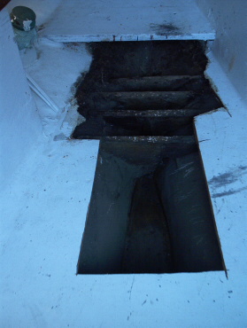
Figure 2. Photo taken after the first cut
There was little if any gap at the bottom of the braces so that any water that went over the front of the cuddy floor was trapped between the braces.
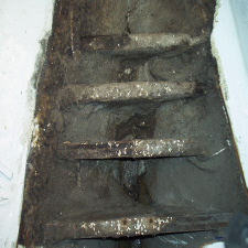
Figure 3. A more close-up view of the braces (floors)
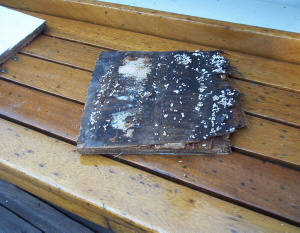
Figure 4. The cuddy floor, or cabin sole, that had rested on the braces was badly deteriorated from the moisture
At this point I spent some time congratulating myself on initiating this much needed maintenance effort!
I enlarged the floor opening in the cross brace area, marked the brace positions, and constructed a cross brace gauge to give me a sense of brace height.
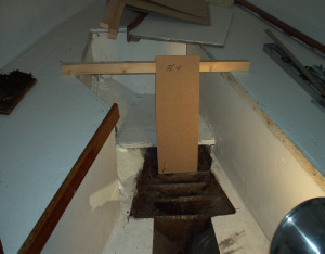
Figure 5. The cross brace gauge. I made four of these: one for each brace
I then used a reciprocating saw to cut through the braces. A little push-pull combined with hammer and chisel took out most of the cross brace material and the floor edges which were fiber glassed to the hull. I then used a grinder to smooth out the hull area where the new braces would be placed. There are two very important words for this part of the process: DUST MASK. The cabin is a very confined space and fiberglass dust will fly everywhere. In addition, I was working under the winter cover so there was little fresh air.
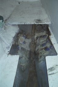
Figure 6. The inside of the hull after grinding away the remains of the braces and fiberglass tabbing
I decided to use a piece of 2 x 3 white oak stock left over from my cockpit floor project in place of the original plywood cross braces. They would be wider than the original braces and would not have the same depth which would increase the bottom opening size to allow for drainage and air flow. The only downside would be the added degree of difficulty in shaping the braces to the curvature of the hull and the narrowing taper going forward.
The next step was to prepare templates for the new braces. The positions had been previously marked. The major question was how high they should be. The cross brace gauge was a good guide, and I was able to project the level of the floor forward by placing a long level on a flat board which I wedged under the center cut in the floor. After constructing a cardboard template, I used a jig saw to cut the curvature into the replacement oak frame. I then used a small drum sander on a power drill to form the tapered shape needed to match the narrowing form of the hull. It was a process of sand, try, test with a level, and repeat until a good match was obtained.
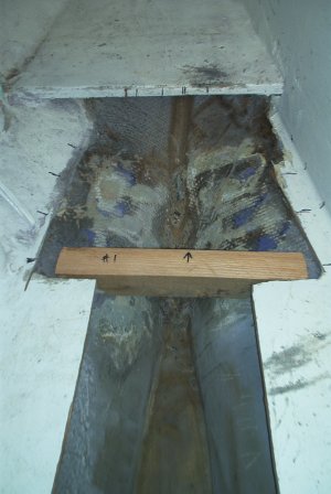
Figure 7. First brace cut and fitted
This was done for all four new braces. I did not try for perfection, as small gaps would be filled by thickened epoxy during the final installation process. I found that the hull curvature was very consistent, so I was able to easily adopt the template for brace #1 as the template for brace #2, then for #3, and then for #4. At this point the project halted for the winter.
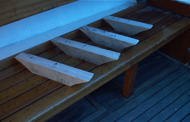
Figure 8. Four newly cut braces ready to go. Ready to wait for warm weather.
With spring came the return of warm weather temperatures for fiberglassing. I used the West System and found the single stroke pump system to be extremely convenient. The first move was to put the new oak cross braces into place. I made up a batch of epoxy of about peanut butter consistency using 404 West filler with the West 105/206 system, trowelled it on the brace ends and set them in place. A small level was used to check the side to side placement, and the longer level was used to check the placement projecting the cuddy floor forward.
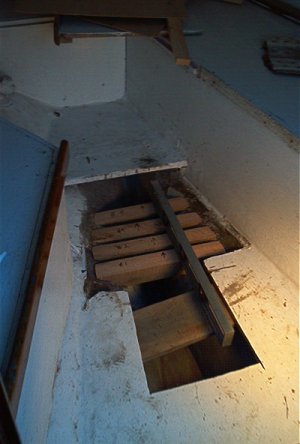
Figure 9. Long level used to project the floor level forward
Fiberglass cloth and unthickened epoxy was then used over the ends for added stability. Additionally, I had previously given the raw braces a coat of resin for added protection against moisture.
With the new braces in place, it was now possible to make a template for the replacement floor piece. I purchased a small piece of plywood which I was assured had exterior grade adhesive. After using a jig saw to cut out the new piece with the help of the template, I gave the piece a coat of resin for added protection. Before installing the new piece, I added a new cross about half way in the new opening for added floor support.
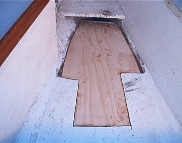
Figure 10. Replacement floor piece installed
The new floor piece was then glassed in with cloth and several resin coats, and finished with a one-part poly paint. I then used the piece of wood T square gauge that I constructed at the start of the project to see whether I achieved my objective to put the floor height back the way it was before. I'm pleased to report that it was within a whisker.
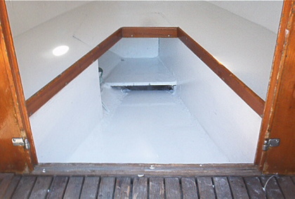
Figure 11. Finished Project (before mast step plate installation)
The final step was to replace the mast step plate. The plumb line from the center of the partner opening gave me my center line dimension. An article in my Ensign archives detailed the distance from the center of the forward bolt to the step leading into the cabin as 36”, so that’s where it went.
All in all, I think I spent more time worrying about the project than doing it. But that's the way it is with first time projects that will probably never be done again. Stated differently, if you think you have a mast step problem, don't wait for a complete failure and the possible loss of your mast. If I can do it, I know you can too.
Contact us if you'd like to learn more about Ensign sailing.