Stern Deck Repair of Ensign #23
Editor's Introduction
In May of 2015, Harold and Carol Klein of Plattsburgh, NY donated Ensign #23, "Daddy" to the Saratoga Sailing School, a program of the Saratoga Lake Sailing Club. While the boat was in generally good condition, especially considering that is was over 50 years old, SLSC members Bruce Blackie and Dave Miller decided it would provide an even better sailing experience for our students if certain items on the boat were repaired.
Dave and Bruce are long time members of Ensign Fleet 72 at SLSC. Bruce is the founder of Fleet 72 and was Captain of Fleet 72 for about 10 years before handing the position over to Tony Cannone. Dave is currently Treasurer of Fleet 72. They have each made major repairs and improvements to their own Ensigns. A few years ago they jointly purchased Ensign #114 and lovingly and beautifully restored the boat part time over several years. #114 was sold to new SLSC members Mary Beth and Paul Fowler, and Dave & Bruce now needed a new challenge. We are glad they decided to apply their skills to the stern deck repair of Ensign #23.
The text and photos that follow were provided by Bruce and Dave.
Vic Roberts
August 2016
Stern Deck Repair of Ensign #23
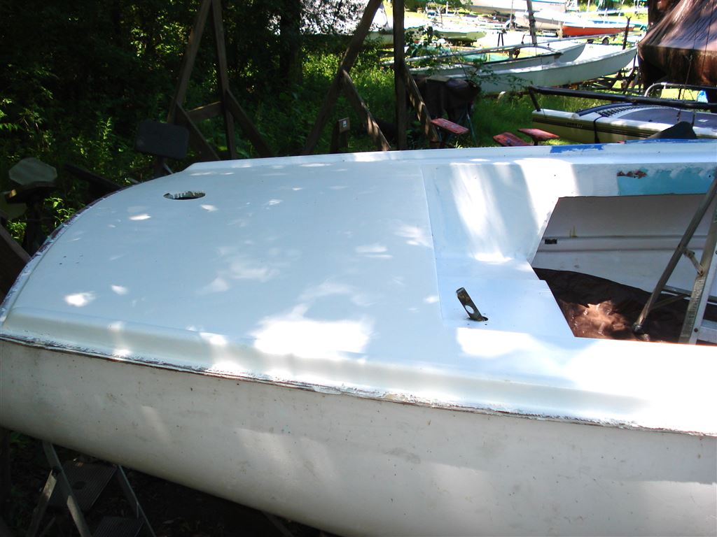
The construction of the decks and cabin top on the Pearson Ensign can best be described as a sandwich consisting of a balsa core between two layers of fiberglass. This creates a rigid structure that is much lighter than if it were constructed of solid fiberglass. On the down side, water can penetrate the sandwich and rot the balsa core. On Ensign 23 this water penetration has occurred and has resulted in a soft and spongy stern deck that compromises the safety and security of all the stern deck hardware and the deck itself.
Bruce Blackie and Dave Miller (that’s us) have undertaken this project to correct the soft stern deck condition. Essentially the stern deck will be removed from the boat. The rotted balsa core will be taken out and replaced with closed cell foam. The reconditioned stern deck will then be reinstalled to the hull. We also have a few other related ideas that will update the control lines on this very early vintage Ensign, and bring it up to par with other Ensigns in Fleet 72. But that will be later in the project.
We are creating this pictorial narrative for informational purposes only and certainly not as an instructional manual. It is intended for anyone that enjoys messing around with boats, and enjoys the satisfaction of following a project from beginning to end. We sure do.
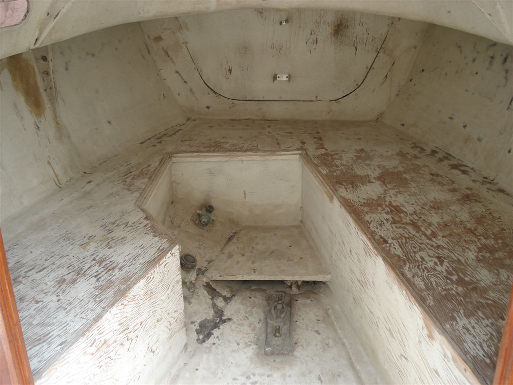
The Start (Fall 2015)
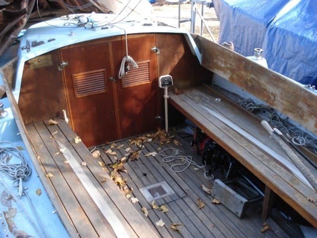
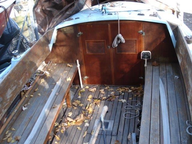
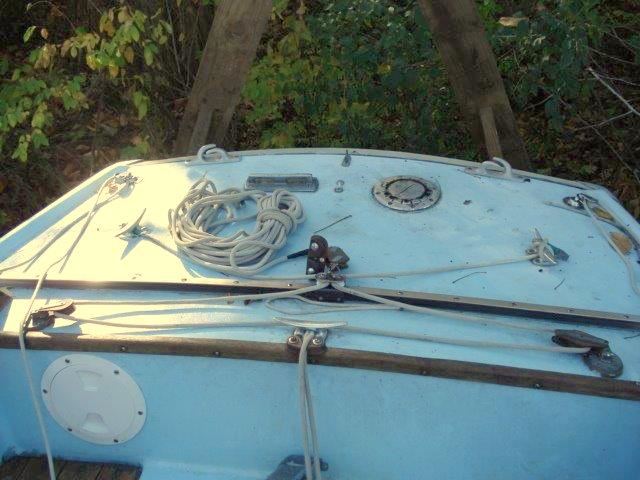
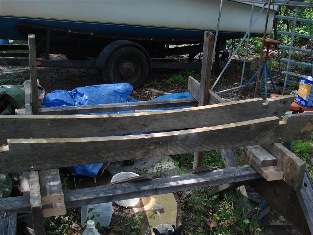
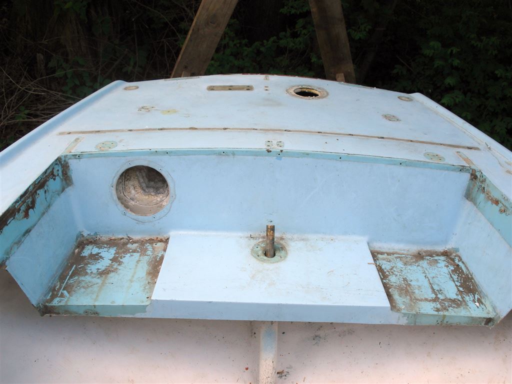
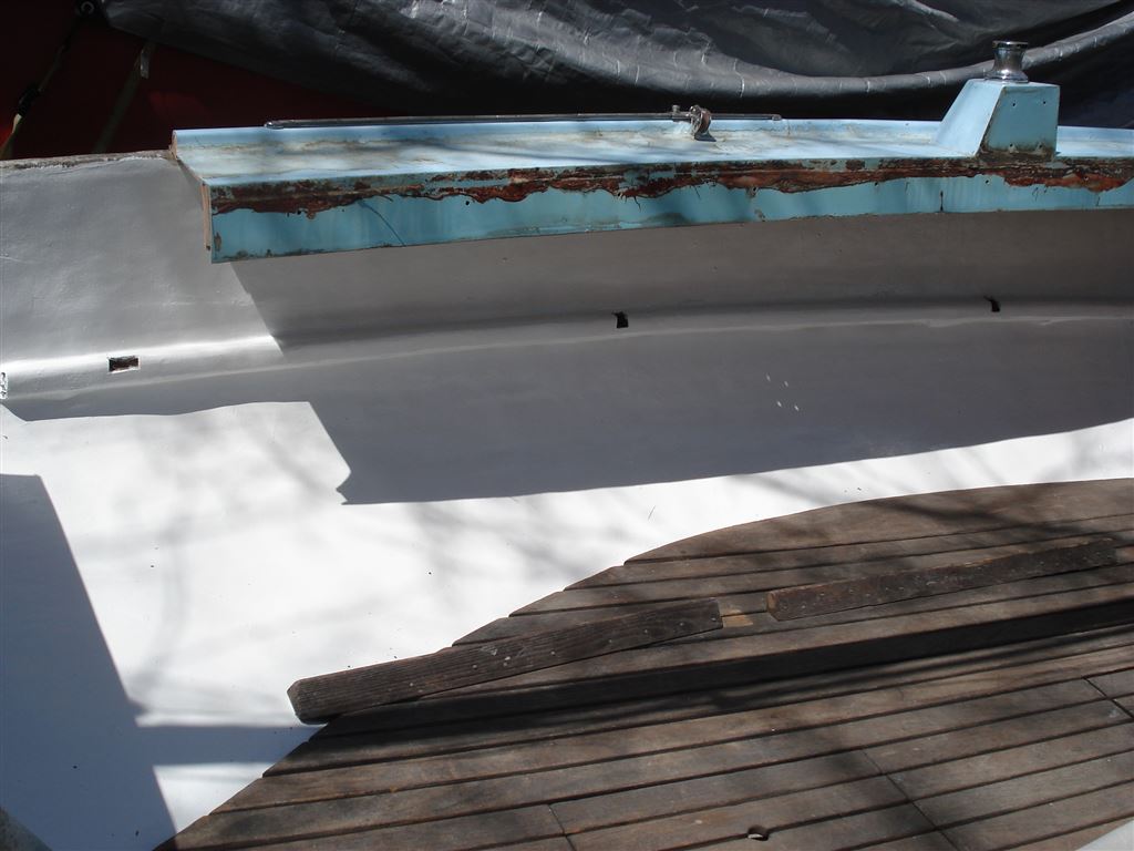
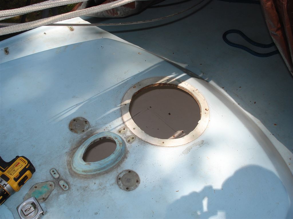
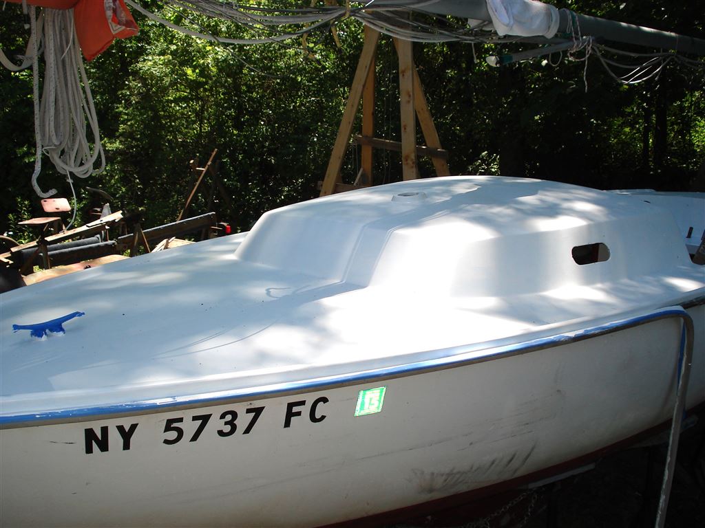
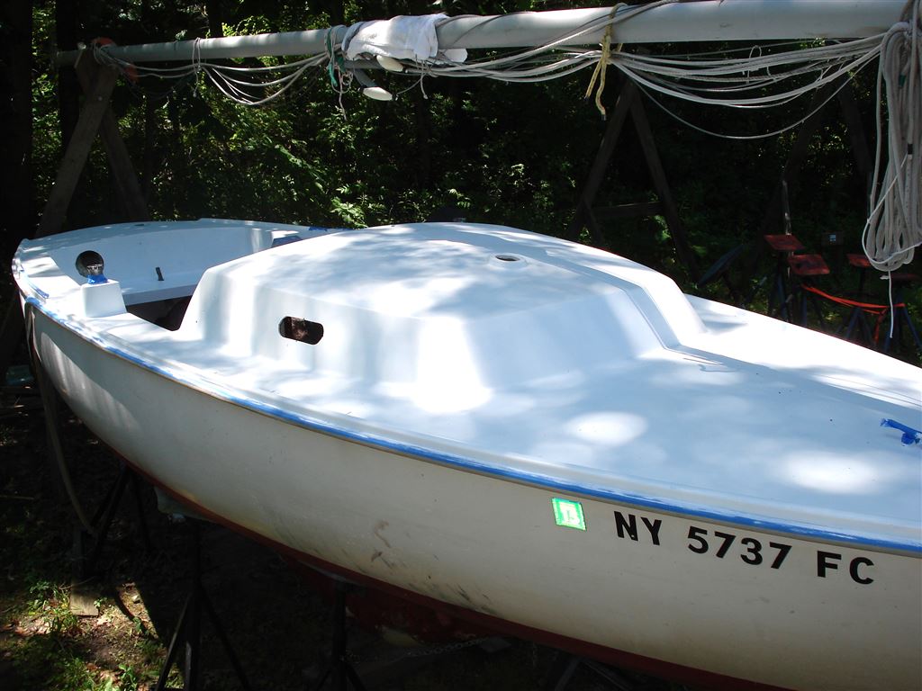
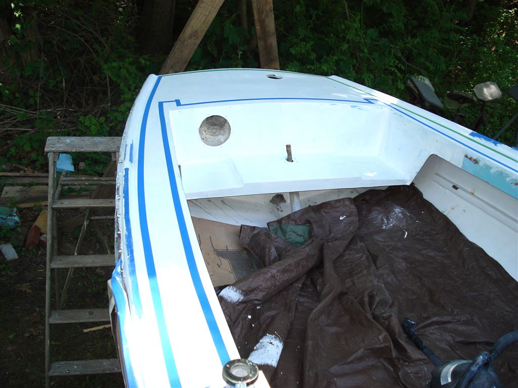
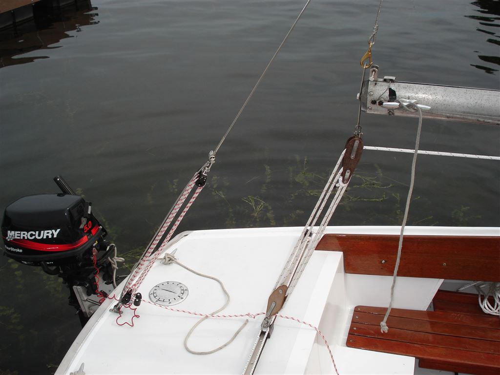
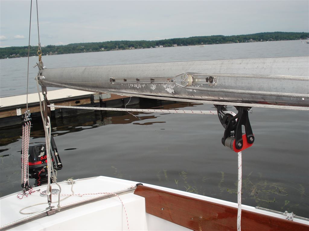
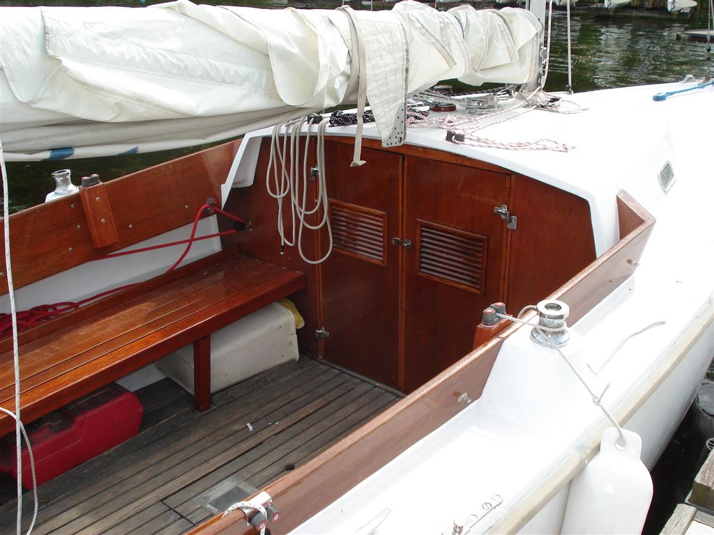
This first group of pictures shows the cockpit and stern area of Ensign 23. This is where our activities will take place and will be a nice comparative when we complete the project.
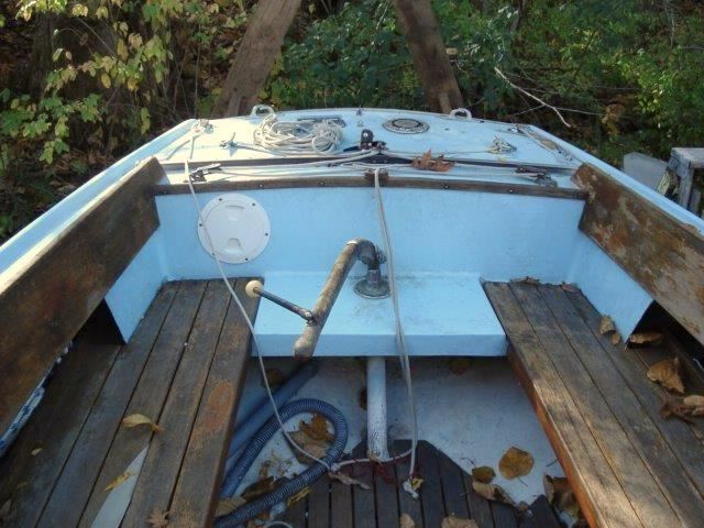
Preparation
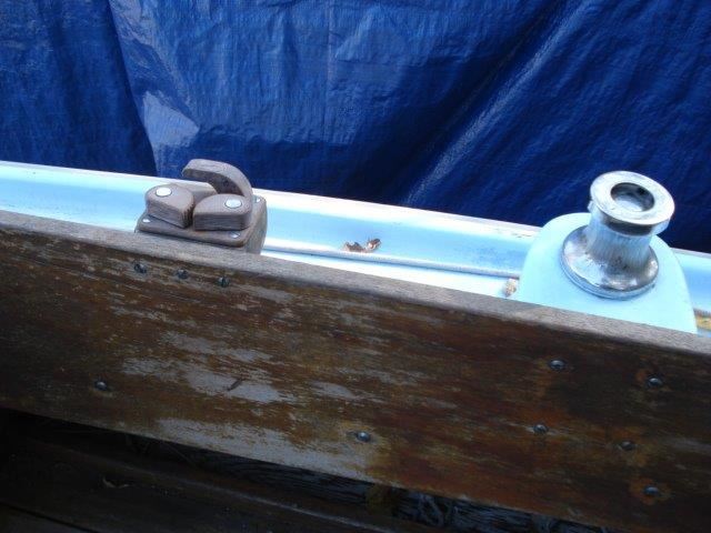
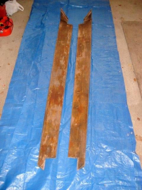
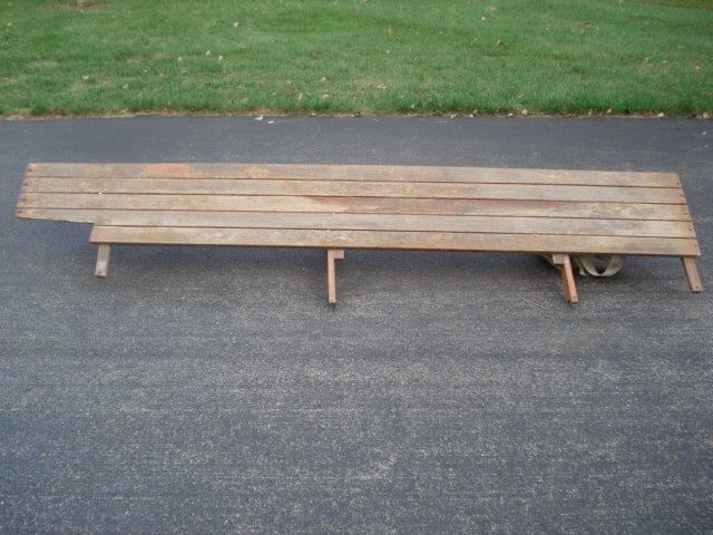
The mahogany cockpit coaming, seat assembly, and the shelf under the side deck must be removed. We will set them aside to be refinished over the winter. Also the rub rail must be separated from the hull flange, and the tiller-head assembly must be removed from the stern deck section.
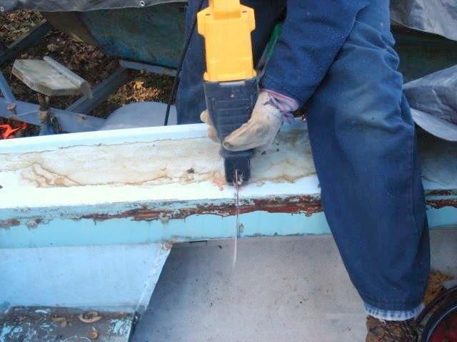
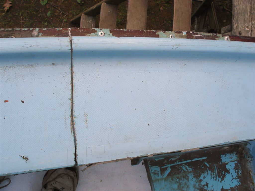
Making the Cut
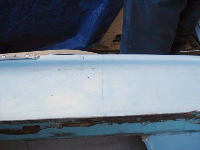
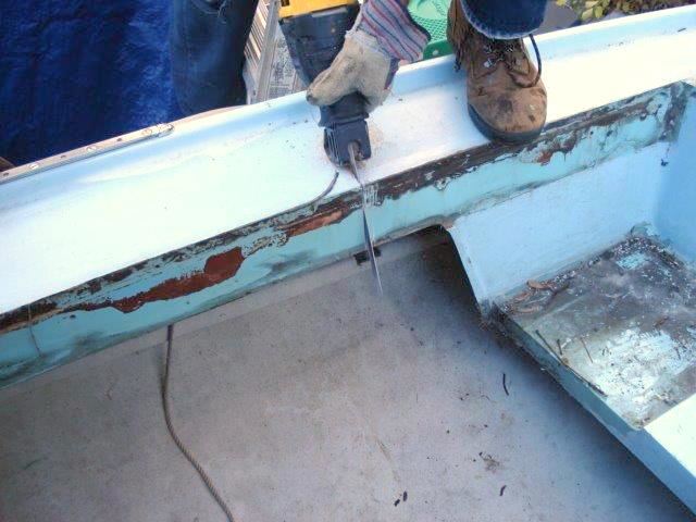
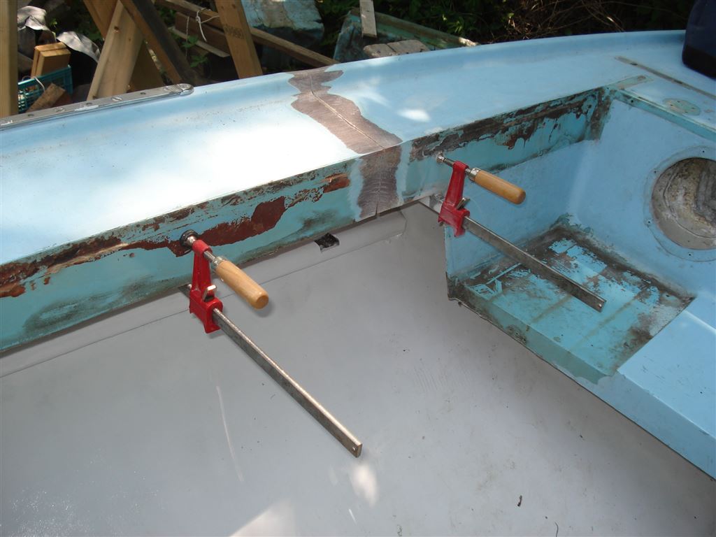
The first cut is thru the side deck. A line is chosen that falls in between the holes for the coaming fasteners and also between the rivets that secure the flange that joins the hull to the deck section. Then you power up the Saws-All and start cutting. When you reach the flange you want to be careful to only cut the deck section component of the flange and not the hull section flange.
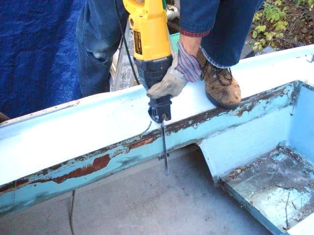
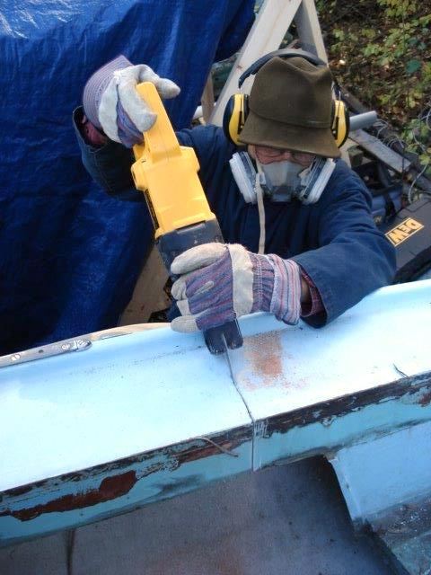
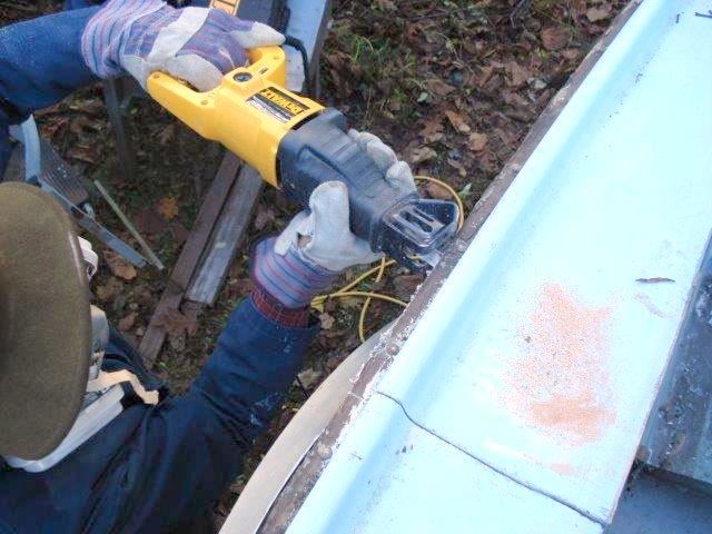
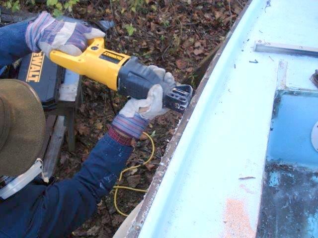
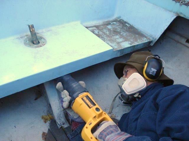
Next begins the deck separation. The saw is inserted into the flange to separate the adhesive/sealant and cut through the rivets that secure the flange. This separation cut is continued around the entire stern-deck to the opposite side. Then the cut is made through the other side deck.
The final cut is made around the rudder shaft tube taking care not to cut into the rudder post that is inside of the tube.
With a few tugs and pulls the stern deck section is now ready for removal from the boat.
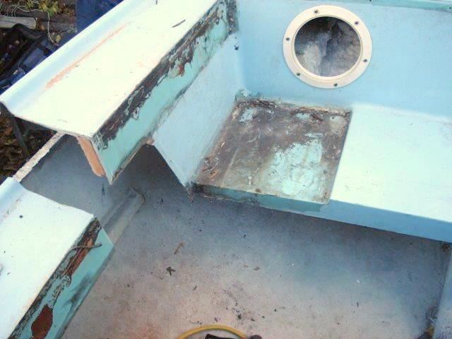
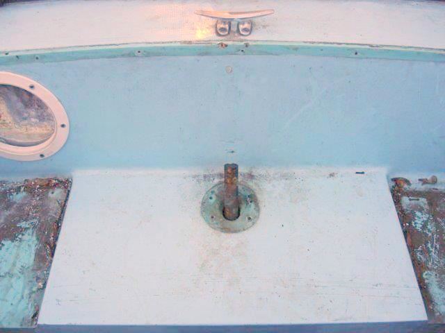
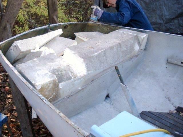
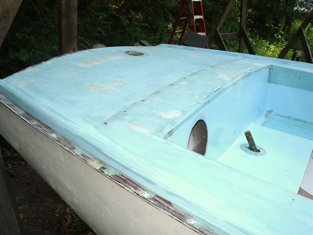
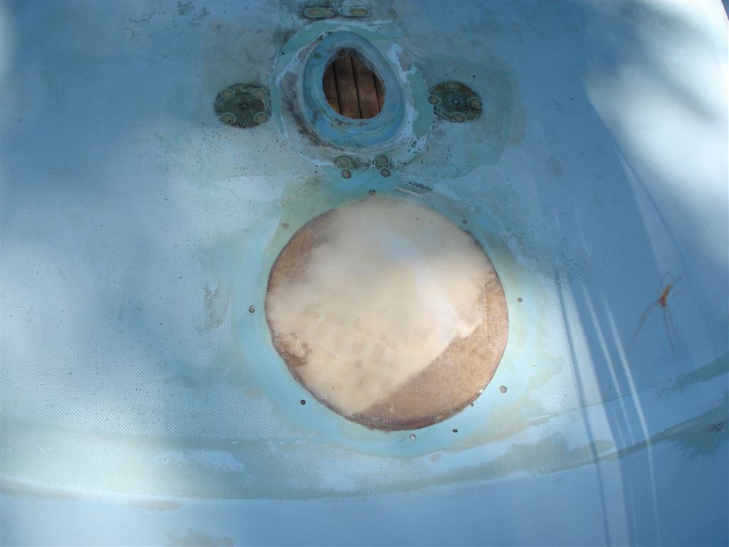
This is a view of #23 without the stern deck. The factory installed flotation blocks are clearly visible and look to be in good condition for reinstallation.
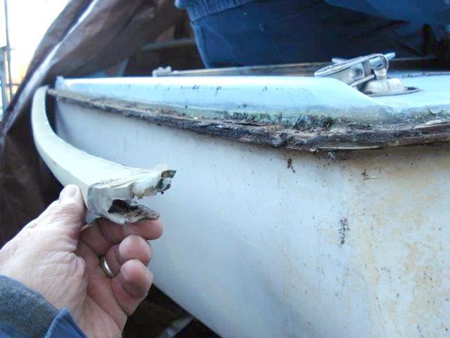
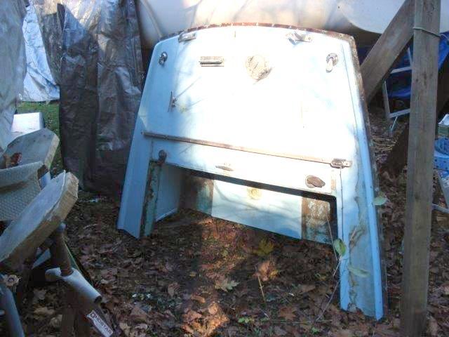
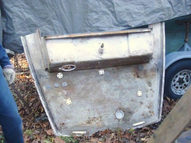
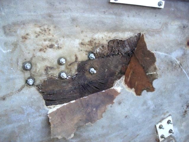
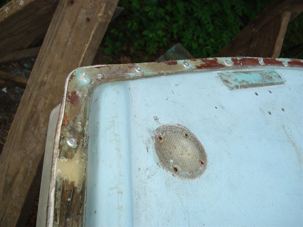
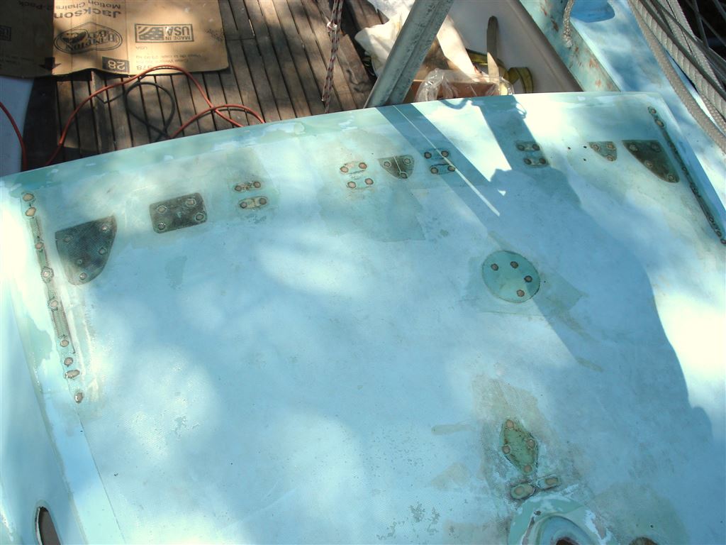
This is the underside of the stern deck. You can see backing plates on the factory installed deck hardware and where one traveler end was reinforced this summer through an access port. The balance of the deck hardware was secured by screws. If not bedded properly, screw holes through the deck are a frequent cause of wet and rotted balsa core. In the close-up picture you can see the deterioration and failure under the deck mounted outboard motor bracket.
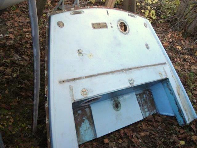
The deck hardware has all been removed and the stern deck will be temporarily placed on the hull for the winter. Next spring, the deck section will be placed on a work station, and the reconstruction will begin.
Spring 2016
With the arrival of spring weather, restoration work on the stern deck could proceed. The first step was to construct a work station to hold the deck section and maintain the deck curvature profile during our balsa core replacement efforts. We used the contoured frames that we had fabricated for the Ensign #114 restoration.
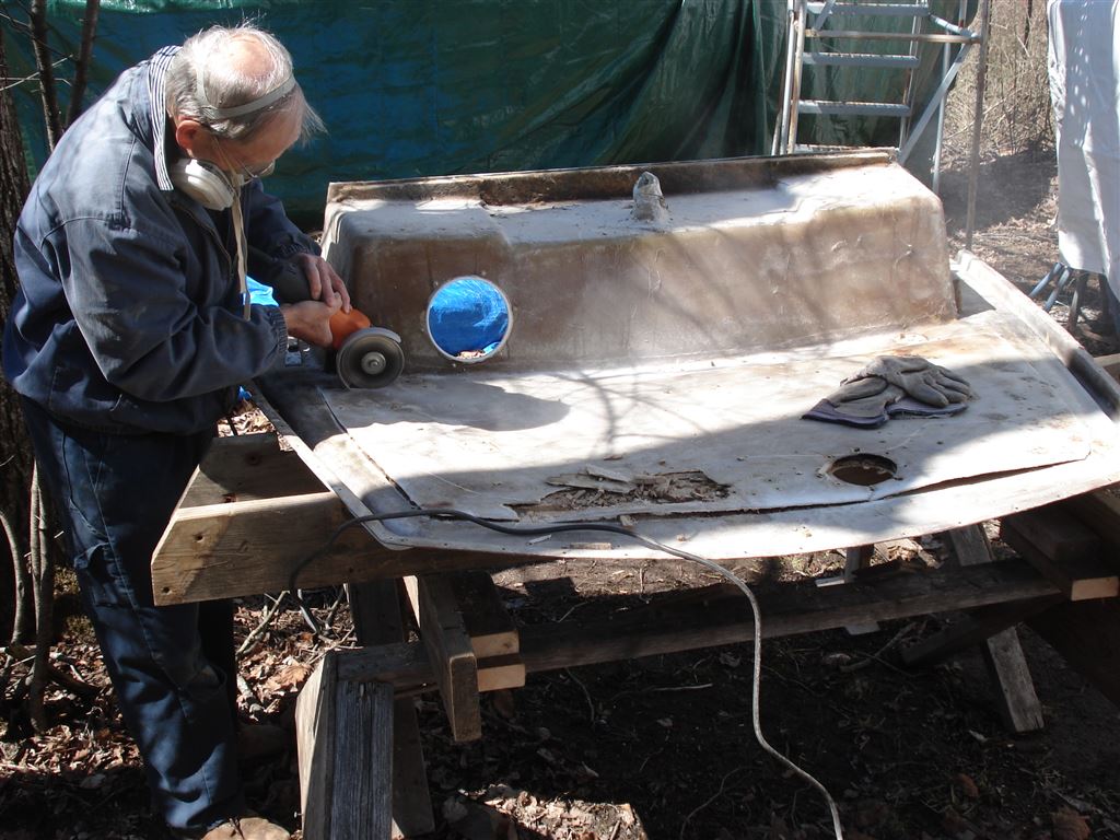
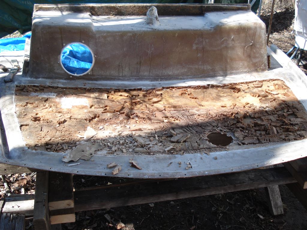
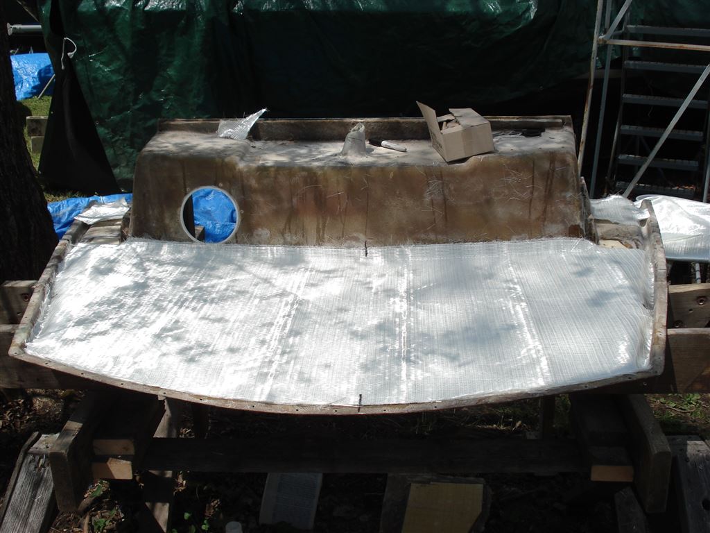
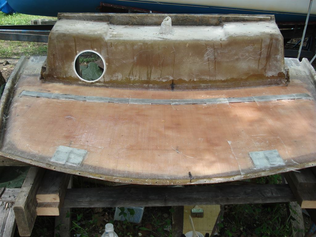
With the stern section on the work station, the now exposed underside layer of fiberglass was cut and removed from the deck section, exposing the rotted balsa core. At this point, removal of the balsa core was easy because it had mostly detached from the fiberglass. A putty knife was the only tool required to remove most of the balsa. A grinder with a sanding disk was then used to remove any remaining residue and give the original fiberglass surface some “tooth” so that new resin would adhere properly.
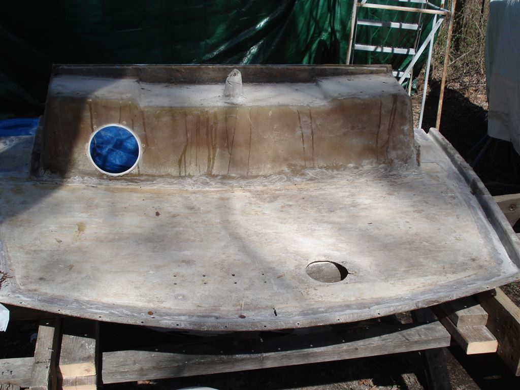
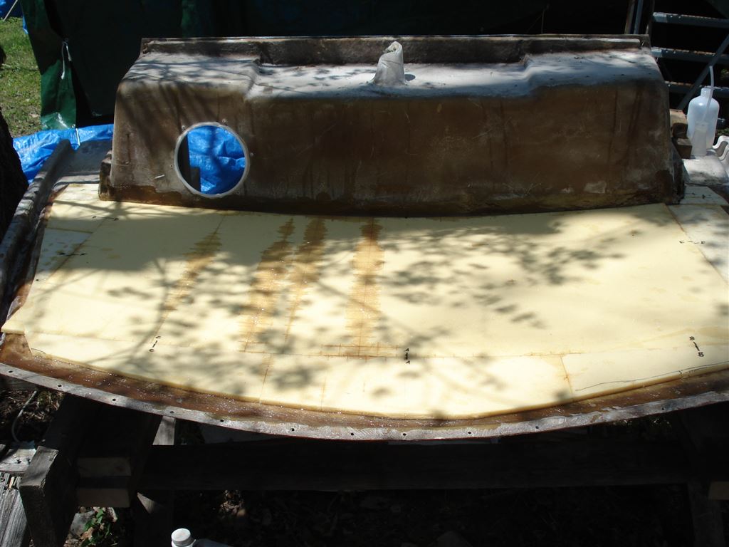
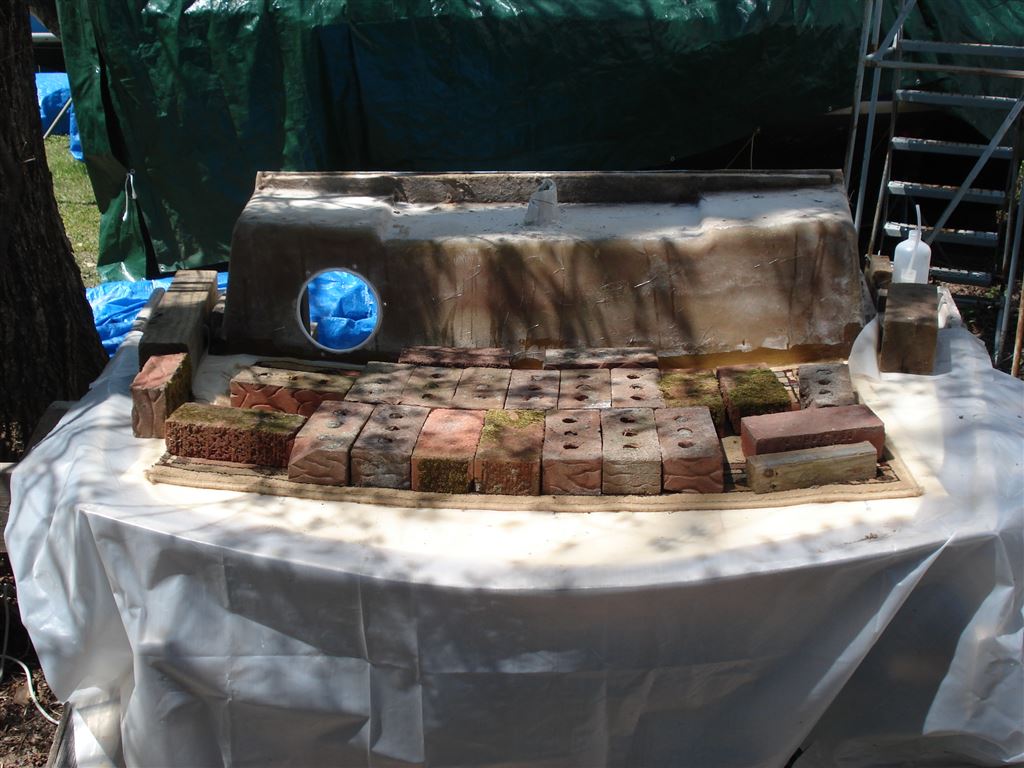
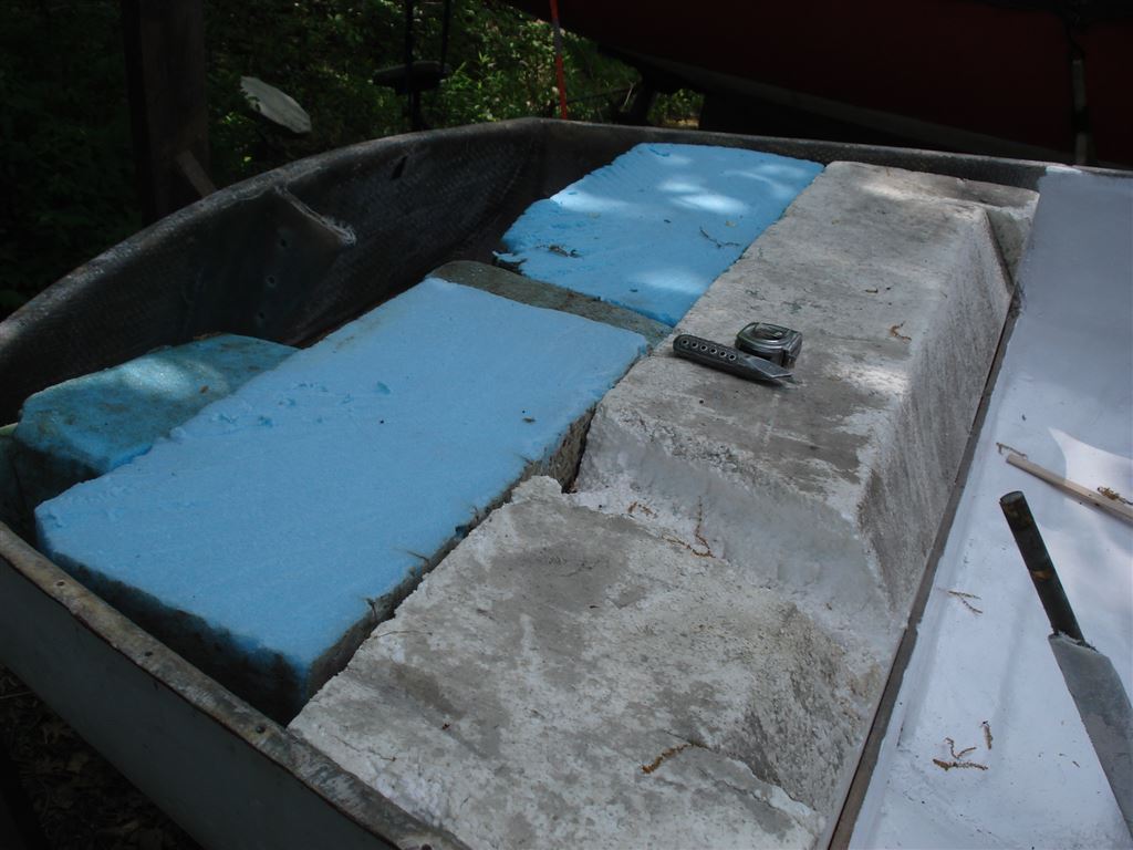
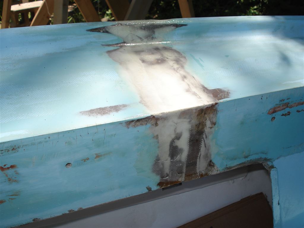
Two layers of fiberglass mat were fitted to the now clean surface and well saturated with fiberglass resin before adding the closed cell foam that replaces the balsa core. Bricks as weights were placed over a sheet of plastic to assure that the new core attains the correct deck curvature.
The now solid new core was faired and two layers of well saturated fiberglass cloth were added to complete the “sandwich”.
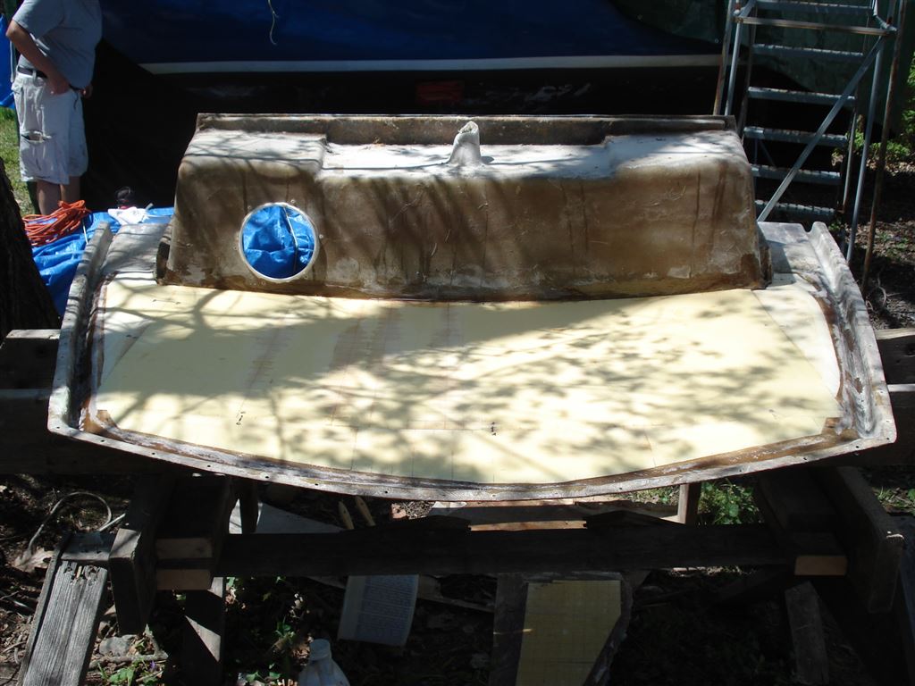
With the newly cored deck now solid, firm and faired, we glassed in aluminum backing plates for the traveler and dock line cleats. When this hardware is eventually installed after assembly of the deck to the hull, we will drill, tap, and thread the plates to receive the appropriate fastener bolts.
With the stern deck removed from the hull, it was an opportune time to add foam flotation, reinforce the transom in the area where the motor mount will be installed and also repair transom areas which had been patched or damaged over the years.
Some minor repairs were made to the hull flange and the rebuilt deck section was replaced on the hull to verify that all alignments were correct. It was then removed and a very generous bead of 3M 5200 adhesive/sealant (aka the devil’s glue) was applied to the hull flange. The deck section was set back in place and rivets were installed in the previous rivet holes.
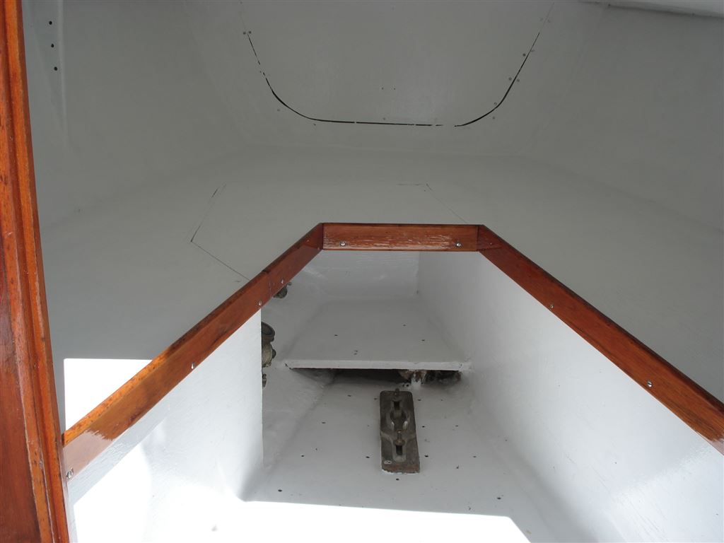
With the cockpit and cabin areas very open due to the removal of the seats, coamings, and chain plates, we cleaned out, primed and painted the cabin interior with one-part polyurethane paint. We also freshened up the cockpit interior with similar paint.
With the deck section secured, our efforts turned to preparations for the deck refinishing, and the blending of the newly joined side decks. The stern tube around the rudder post was also rewrapped in fiberglass. Remaining deck hardware holes were epoxy-filled, faired and sanded in preparation for painting.
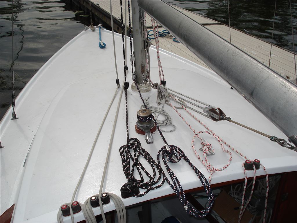
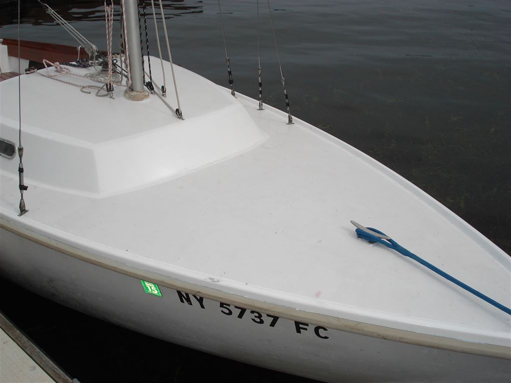
In a classic case of “mission creep” it had been clear to us for some time that we could not limit our refinishing efforts to the stern deck. The cabin top had many original control line fittings that, at the very least, should be removed and caulked to protect against moisture invasion of the balsa core. Also, an oversized cabin top vent opening/skylight was cracked and was an obstacle to any foredeck spinnaker work. It had to go. With a clear cabin top, new control line hardware could be placed in more efficient positions. As for the fore deck, not much was needed, but you can’t stop at the cabin’s edge. However, our closer inspection of the foredeck hardware uncovered a crack in the bow stem fitting that secures the forestay. This obviously required a replacement as a failure under wind pressure would be a catastrophe. As with the stern deck, all cabin top hardware was removed, the holes filled with epoxy, and then faired and sanded in preparation for painting.
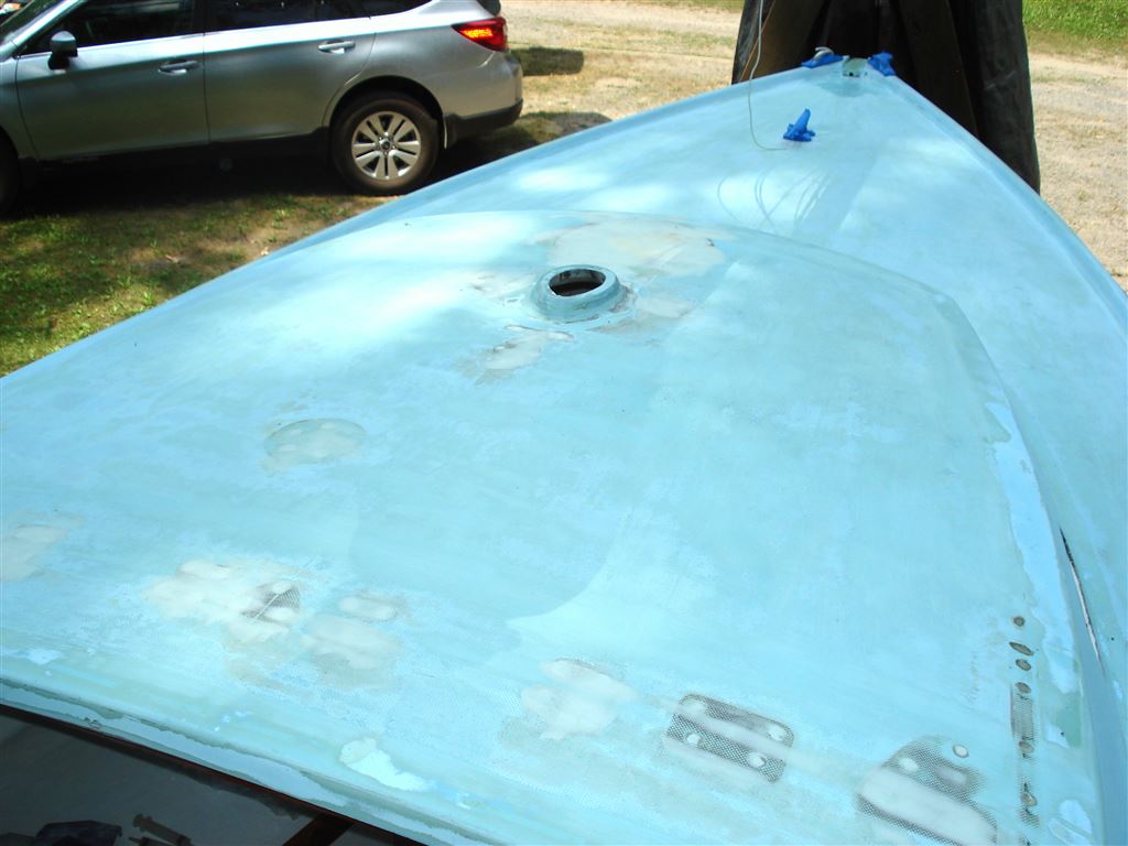
With all the decks faired and sanded, a coat of primer was applied to all the deck surfaces.
The next step in the process was to mask the deck surfaces to define the areas that would be painted with one-part polyurethane gloss paint and then mark the areas that required a non-skid treatment. We used a non-skid additive to the one part gloss paint for the non-skid area.
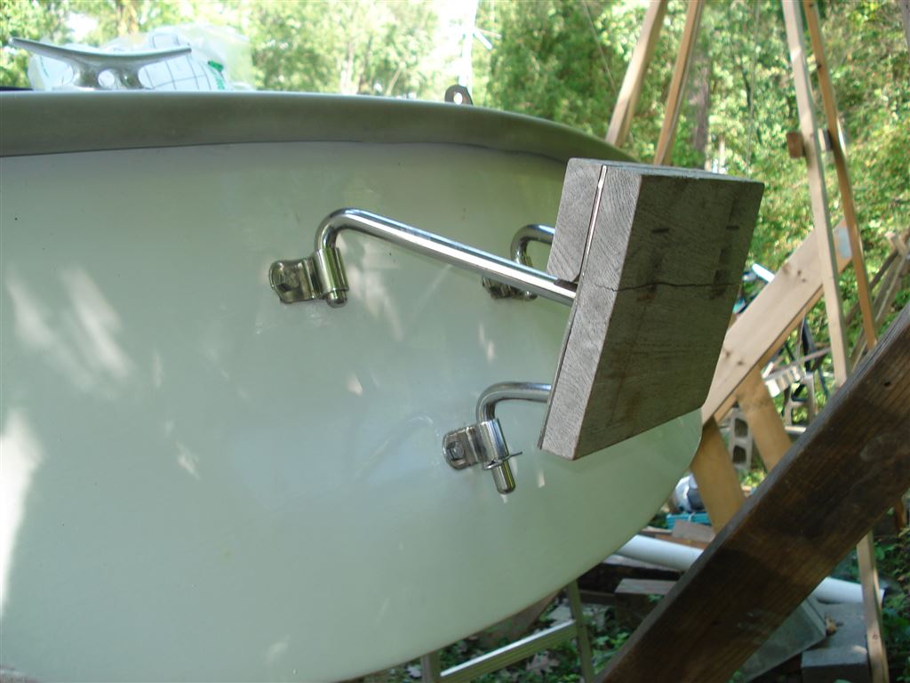
Once the paint dried, we could begin the reassembly process and install the hardware modifications that were now possible. The refinished mahogany coamings and seats were set back in place. An updated motor bracket was installed on the reinforced transom to replace the bulky stern deck mounted motor bracket.
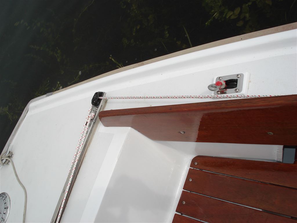
Thru-the-deck spinnaker sheet blocks were installed and lines brought forward under the side deck to a ratchet block on the cabin bulkhead and a cleat on the coaming.

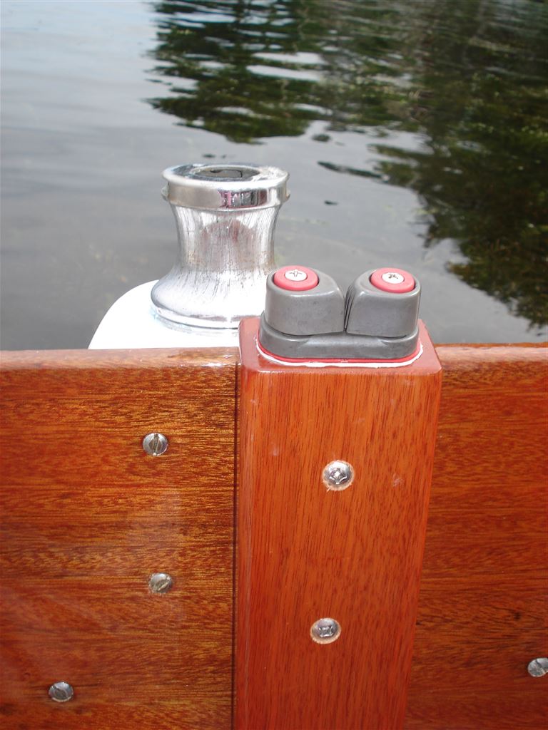
New genoa sheet cam cleats and support blocks were also installed on the coaming.
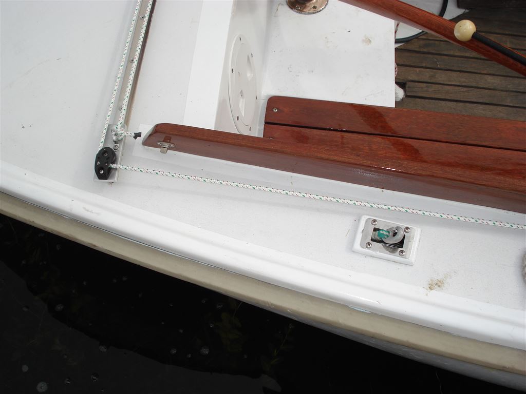
The original traveler was modified by fabricating a support fixture at each end, and mounting a cheek block to lead the traveler line forward to a mid-cockpit position on the coaming. A small cap was fabricated to eliminate the line rub on the top surface on the coaming. Also installed were an adjustable backstay, and a mid-boom sheeting arrangement which includes the appropriately named “head knocker” cam cleat. These modifications make it possible for crew to control the main sail and traveler from the center of the cockpit.
The cabin top running gear hardware arrangement is much more efficient than the prior layout.
Overall, we are very pleased with the appearance of our work.
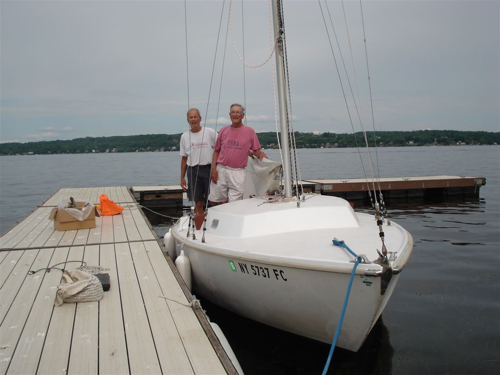
A huge “thank you” to Paul, Tony, Piotr, and Scott who pitched-in with the final on-the-water commissioning activities of mast stepping, securing the shrouds, installing the running rigging, problem solving, and taking care of all the other miscellaneous but critical stuff that can happen.
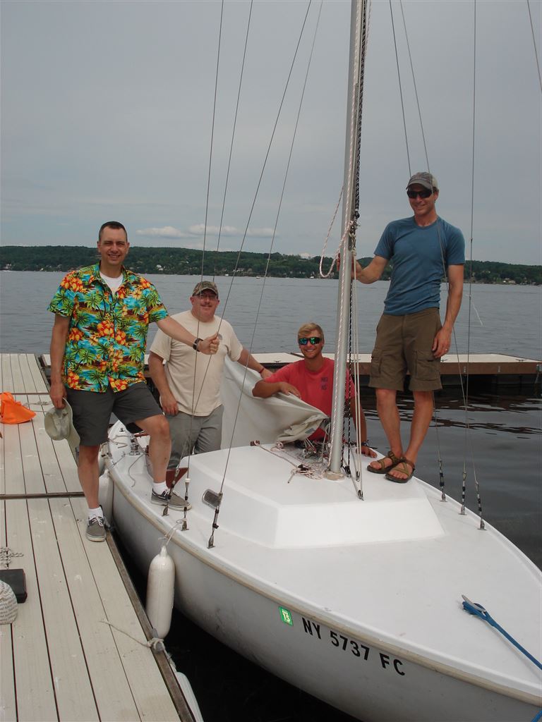
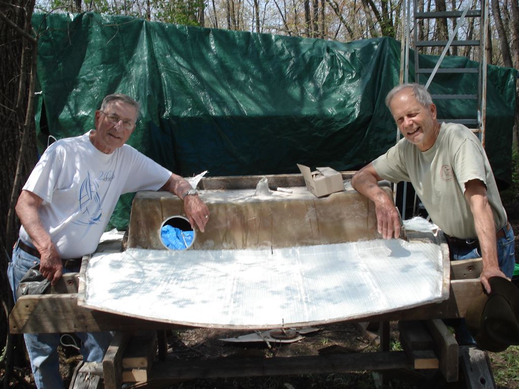
And finally, this is us, Dave and Bruce, as we look over the results of our efforts of the past several months and think, “not bad.” It was a lot of work, but we enjoyed the process and are pleased with the result.